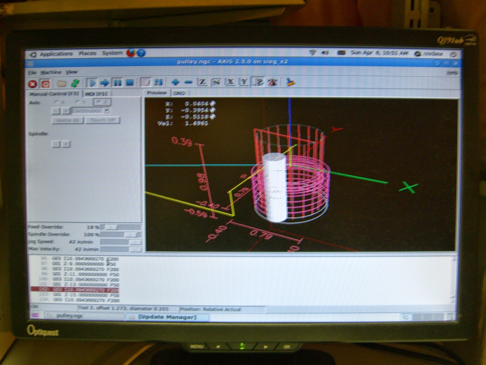
I wanted to try this method out on my mill, but rather than manually draw out the part, I decided to write a C# application that would do the calculations for me and generate the g-code. It's coming along, and so far I've milled a handful of pulleys with dimensions that were close but not a perfect fit. I still need to tweak the calculation for the outer diameter and tooth position slightly so that the belt teeth enter and exit the gaps in the pulley easier. I should be able to get this worked out in the next few days.
In the meantime, here is what the application looks like so far, and a couple of the test pulleys I milled.
 |
| Pulley Creator for a 3 Axis Mill |
 |
| Sample g-code Output from Application |
 |
| MDF Milled Test Pulleys for a GT3 Belt |
UPDATE 1:
I managed to find the issue with the calculation of the outer diameter in the original algorithm. The first was in the calculation of the outer pulley diameter. The circumference of the outer diameter was not passing through the center-point of the tooth pulley hole. This leads to the belt not being able to rest on top of the pulley teeth and meshing properly. The difference in this calculation was 3/10ths of a millimeter for this particular pulley.
 | ||
| Comparing Milled Pulley with a Plastic Idler for the Same Belt |
 |
| Teeth Meshing on the Pulley |
 |
| Size Comparison with a Dime |
UPDATE 2:
Added the option of creating a collar for a set screw and optimized the tool path and speeds.


