Welcome to my personal blog. This is just a spot for me to document some of my projects, activities and interests. Have a look around, and if you have any questions you can contact me or drop a comment in the post.
I was hoping to be able to make timing pulleys on my mill with the help of some already available software. Unfortunately, all of the software that I came across require a 4th axis to mill pulleys. I did see one YouTube video of someone who managed to do this by vertically drilling all of the holes first, then milling around the part to expose the teeth. I believe only one part was needed, so he sketched it out in CAD and created the g-code for it.
I wanted to try this method out on my mill, but rather than manually draw out the part, I decided to write a C# application that would do the calculations for me and generate the g-code. It's coming along, and so far I've milled a handful of pulleys with dimensions that were close but not a perfect fit. I still need to tweak the calculation for the outer diameter and tooth position slightly so that the belt teeth enter and exit the gaps in the pulley easier. I should be able to get this worked out in the next few days.
In the meantime, here is what the application looks like so far, and a couple of the test pulleys I milled.
Pulley Creator for a 3 Axis Mill
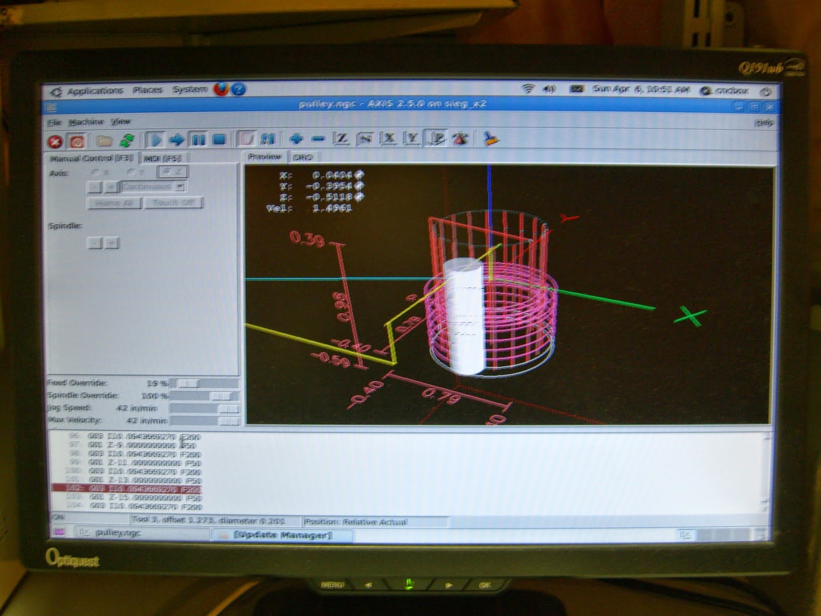
Sample g-code Output from Application
MDF Milled Test Pulleys for a GT3 Belt
UPDATE 1:
I managed to find the issue with the calculation of the outer diameter in the original algorithm. The first was in the calculation of the outer pulley diameter. The circumference of the outer diameter was not passing through the center-point of the tooth pulley hole. This leads to the belt not being able to rest on top of the pulley teeth and meshing properly. The difference in this calculation was 3/10ths of a millimeter for this particular pulley.
Comparing Milled Pulley with a Plastic Idler for the Same Belt
Teeth Meshing on the Pulley
Size Comparison with a Dime
UPDATE 2:
Added the option of creating a collar for a set screw and optimized the tool path and speeds.
A few years ago I bought a Sieg X2 from Harbor Freight in the US with the intention of converting it to CNC. I couldn't pass up buying it for $400 when the equivalent mill sold locally at Princess Auto and Busy Bee Tools for almost double the price.
It sat idle for a couple of years because something always came up that prevented me from working on it. Finally, at the end of last year I started to piece together a plan of how to complete the conversion. There are a couple of bolt-on kits that you can purchase, but I figured it would be an interesting project to try and assemble it from scratch.
The first things I purchased were the three ball screws and ball nuts to control the movement. I ended up buying them on eBay from Asia Engineer, along with couplers and six thrust bearings for $180 CAD.
Next was to disassemble the mill so that I could begin fitting the ballscrews. I started with the X-axis since I thought it would be the easiest to modify since I could re-use the end plate that houses the thrust bearings.
After a bit of work with a Dremel, I managed to cut down the ballnut enough to clear the channel. One thing I didn't realize was that there was an exposed grease hole that was now filled with metal filings. I had no choice but to disassemble and clean it... a complete pain.
I managed to find a good deal on the stepper motors (425oz-in), drivers, and breakout board from eBay for $325 CAD from wantaimotor. The motors are more than sufficient, and the drivers look very well made with aluminum heat sinks.
Not having the right tools for metal work made this job a bit harder. All of the motor mounts and aluminum work was done with a hack saw, Dremel tool and a drill press. If I only had a mill to make the parts, things would be so much easier :)
Next I worked on the Y-axis. Before starting the fitting, I needed to open up the throat so that I would not lose any travel since the new ballnut was larger than the original leadscrew nut.
Both the Y and Z-axis needed to have the thrust bearing housing made along with the motor mount. With the proper tools, this would be easy to make out of a solid piece of aluminum, but I needed to come up with different approach that would not require any milling. I ended up making the housing out of three separate pieces of aluminum.
A hole saw in a drill press was used to cut the larger holes on the two outside pieces of aluminum. Smaller screws held the three pieces together until the main mounting bolts sandwiched the pieces securely. Duplicating this setup one more time for the Z-axis, and all three ballscrews and motors were mounted.
Some details about the Z axis of the machine. There is a plate attached to the top of the Z column that extends off to
the right side of the machine by about 3 inches, and extends forwards
(towards you if you are facing the machine) about 1 1/2 inches. This is
where the Z axis stepper motor mount is located.
Underneath the 1 1/2
inch overhang is another plate that is attached to the top of the Z axis
saddle. This is where the ball nut is attached. Its basically the
same as the Y axis, except instead of the motor and rod being centered
with the saddle, it runs off to the side.
Instead of buying a separate enclosure for the electronics, I ended up mounting the drivers, power supply and breakout board inside the mid-tower case and added an extra fan for cooling.
Today I had a chance to test out the mill by having it draw out the sample file that comes with Linux CNC. Even though the pen was vibrating quite a bit, and stumbled a few times with direction changes, it does demonstrate the capability of the mill.


