The current setup (as with any standard lawnmower engine) was based on a carbureted intake manifold. Students from previous years already modified the engine with a CAM position sensor and had fitted the engine with a motorcycle intake. The reason behind adding a fuel injection delivery system was that the engine could be tuned dynamically to run with less fuel (running the engine "leaner"). After his project was submitted (and final grades were determined), I decided to develop a tunable fuel injection system for this engine.
The sensors that were available were a TPS, O2 sensor, and TMPS. A helpful addition would have been a MAP (manifold absolute pressure) sensor, however the intake manifold at the time was not modified to accommodate one.
Functional Descriptions of Sensors
TPS (Throttle Position Sensor): The throttle position sensor determines the open angle of the throttle plate. This information is used to detect if the throttle plate is closed, wide open, partially open, and the rate of change of throttle position. The sensor is basically a potentiometer with an overall resistance of 5,000 ohms, +/- 25%.
O2 (Oxygen) Sensor: The oxygen sensor monitors the level of oxygen (O2) in the exhaust so an onboard computer can regulate the air/fuel mixture. The sensor is mounted in the exhaust manifold and generates a voltage signal proportional to the amount of oxygen in the exhaust. When the air/fuel mixture is rich and there is little O2 in the exhaust, the difference in oxygen levels across the sensing element generates a voltage through the sensor's platinum electrodes: typically 0.8 to 0.9 volts. When the air/fuel mixture is lean and there is more oxygen in the exhaust, the sensor's voltage drops to 0.1 to 0.3 volts. When the air/fuel mixture is perfectly balanced and combustion is cleanest, the sensor's output voltage is around 0.45 volts.
TMPS (Temperature Sensor): The temperature sensor is used to monitor the temperature of the air/fuel mixture in the intake manifold. It uses this information, in addition to the manifold pressure, to calculate the density of the air entering the engine.
MAP (Manifold Absolute Pressure) Sensor: (Would have been nice to have) The MAP sensor determines the absolute pressure (not the relative-to atmospheric pressure) of the air inside the intake manifold and the atmosphere (barometric pressure).
Here are a couple of close-up pictures of the motor and intake manifold. In the picture on the left, you can see the fuel injector clearly. The Temperature Sensor is not visible as it is located on the opposite side of the intake at the position marked "TMPS". Also, the Throttle position sensor is on the opposite side of the throttle plate CAM (marked "TPS").

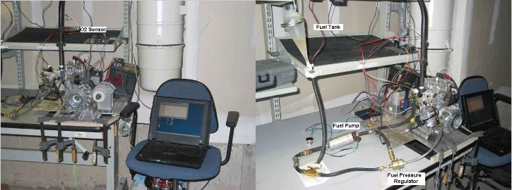
Here are a few more pictures of the complete setup. In the picture below on the left, you can see the O2 sensor mounted on the exhaust pipe to the left of the position marked "O2 Sensor". In the picture below on the right, you can see the fuel tank, fuel pump and fuel pressure regulator.
There were several steps involved in setting up the fuel injection controller. Let me summarize the steps below:
The throttle plate open angle was divided into 500 positions. The first objective was to determine the base injector "on time" which was the minimum on-time required to keep the engine running while at idle. This number was finalized once the engine had been running for a period of time long enough to warm up the O2 sensor to its operating temperature.
Next, each of the 500 throttle plate positions required tuning to the proper injector on-time (this was the most tedious part of the setup). The injector on-time was tuned so that the O2 sensor would report a less than perfect air/fuel (lean) mixture (approx. 0.3V). This became the "base" or "ideal" injector on-time for the engine. The settings for each of these positions were stored in the EPROM of the micro controller.
Cold starts required more fuel to get the engine running. After a few cold start attempts, the delta was determined and added to base injector on-time. As the engine warmed up, so did the air entering the cylinder which resulted in less fuel needed for combustion. The TMPS would be used to gradually reduce the delta to zero, bring the injector on-time back to the preset "base" timing.
The only trouble point that remained was when an abrupt change in the throttle position was encountered. Since the engine was already running lean, quick changes in the throttle plate position (opening) would cause the engine to cut-out. The solution to this was to add another delta that would increase the injector on-time to prevent the engine from stalling. Ideally, if you are trying to keep fuel consumption down, quick acceleration should be avoided. Once the throttle plate had stabilized, the controller would slowly return the engine to the default "base" timing.
The Fuel Injector controller was also equipped with a RS-232 port. All of the settings including the fuel map, cold-start delta, throttle plate delta could be accessed, modified and stored using a lap-top computer. This allowed the engine parameters to be "tweaked" if needed on the spot without having to recompile and flash new software. The port could also report the status and readings of each sensor to validate proper operation.
Here are a few pictures of the Fuel Injection controller board:

May 23th, 2003
No comments:
Post a Comment